
Wastewater Treatment Tutorial
Domestic Sewage Treatment Systems Tutorial
Information on the design, installation and maintenance of individual home sewage treatment systems. It is meant to be a homeowners reference document.
An individual sewage system both treats and disposes of household wastewater. If a homeowner understands how the various components of a home sewage system work, then a properly designed and installed system will function for many years with a minimum of maintenance and upkeep.
Home wastewater enters the sewage treatment unit, which separates solids from liquids. The sewage treatment unit is a “bioreactor” where micro-organisms break down organic matter in the wastewater to liquids, gases and solids. Gases are vented off through the house vent stack. Sludge accumulates in the sewage treatment unit and must be removed periodically.
The five parts of a sewage disposal system are: (1) the house plumbing, (2) the sewer line from house to sewage treatment unit, (3) the sewage treatment unit, (4) the sewage treatment unit outlet sewer pipe, (5) the sampling chamber and (6) the final soil treatment unit or pipe to watercourse. All individual sewage treatment systems must comply with regulations. A Consent to Discharge is required before constructing a new home sewage treatment system or when repairing an existing system.
Generally accepted safe distances from the system and features are shown in Table 1.
When the sewage treatment system is installed, make a map of the installation. Measure and record distances from the sewage treatment unit, drains, inspection chambers and soakaway to aboveground features such as buildings, fence corners or large trees. Then after the area has grassed over, you still can find the component parts of the sewage system.
Table 1. Separation distance between the treatment system components and water sources (all distances in metres
| Item | Sewerage Min/Max | Treatment Min/Max | Drainage Min/Max |
| Well under 30 metres deep | 50 | 50 | 50 |
| Watercourse/Ditch | 10 | 10 | 10 |
| Distance from roads | 0/0 | 30/4 | 0/2 |
| Property Boundaries | 0 | 2 | 2 |
| Dwellings | 0 | 7 | 15 |
The House sewer pipe should have a slope between 1:40 and 1:80. On too flat a grade, the liquid will slow down, allowing the solids to settle out in the sewer pipe. On too steep a grade, the liquids will flow away from the solids.
The sewer line from the house to the sewage treatment unit is usually plastic sewer pipe with waterproof joints If using plastic pipe, The joints must be watertight and resist root penetration.
The house discharge sewer must be at least 110mm diameter pipe.
Don’t make sharp bends in the house sewer system unless absolutely necessary. Inspection chambers must be installed on every bend/confluence of pipes.
Never, under any circumstances, allow surface water drains to discharge into the house sewage system. This will overload the system.
Sewage treatment plants
Sewage treatment units have been used for on-site wastewater treatment for more than 30 years. There are many different types
The material in the sewage treatment unit separates into three distinct layers:
The liquid discharged from a sewage treatment unit is called effluent. Effluent from a properly maintained sewage treatment unit is clear and odourless and contains very fine suspended solids, bacteria and nutrients.
All household wastewater must go to the sewage treatment unit. Household wastewater sometimes is referred to as “black water” or “grey water,” depending on which appliance or fixture it came from. No matter the source, do not let water and other similar wastes bypass the sewage treatment unit. Grey water containing soap or grease sent directly to a soakaway will plug the soil pores quickly.
Sizing
For a house, the required working capacity is based on the number of bedrooms, not the number of people in the house at the time of construction. A 3 bedroom house is sized as requiring a 5 person unit, with 1 extra person per additional bedroom
Location and Installation
The sewage treatment unit should be at least 7 to 10 metres away from the house. The tank should be aligned straight out from the point where the discharge sewer line leaves the house. Installing the tank so it is level, with no slope in any direction, is important. For pumping and cleaning, the sewage treatment unit should be situated near a driveway or other access road. Most tanker trucks carry between 20 to 30 metres of hose, so the tank should be accessible from this distance. Select a location away from high vehicle traffic areas. Never locate sewage treatment units under decking or patios where the tank is inaccessible for pumping.
Construction
Sewage treatment units are built using corrosion- and decay-resistant materials. If installed properly, they will be watertight for a long time (20 years or more) Fibreglass and durable plastic sewage treatment units are the most common. They must be installed by carefully following the manufacturer’s instructions so they will withstand soil and water pressure. Many have to be surrounded in concrete for strength.
Sewage treatment units must be cleaned regularly to remove the sludge that accumulates in the bottom of the primary tank. For most houses, cleaning every year is satisfactory. However, a house with a garbage grinder that the occupants use may require a 6 monthly cleaning interval. Garbage grinders increase the organic matter flowing into the sewage treatment unit.
Sampling Chamber
A sampling chamber must be installed after the sewage treatment unit in order that samples of fresh effluent can be taken. These are available ready-made in GRP or plastic or can be built in-situ using manhole base, rings, cover and frame. The inlet into the sampling chamber MUST be 200mm higher than the running base outlet. This necessitates cutting a hole in the side of a ring, inserting the pipe from the sewage unit 100mm. into the chamber and sealing with waterproof mastic.
Pumping Stations
Pumping stations are required in situations where the effluent cannot flow by gravity and must be lifted to a destination. Many manufacturers make complete ready-to-install pump stations. Pumping is required when the soakaway or watercourse is at a higher elevation than the sewage treatment unit. A mound soil absorption system will require a pumping station. A pumping station consists of two main parts -- the watertight tank and the pumping system that includes the pump, on/off switches, alarm system and wiring.
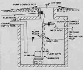
Sewage treatment unit effluent pumping chamber. Working capacity should equal about one-fourth the daily sewage volume. Reserve plus working capacity should equal 24 hours sewage volume. This allows time to correct any pumping problems.
Tanks
The tank containing the pump must be watertight. If not, ground water may seep into the tank and the excess water easily will overload the pump. The tank should have enough volume below the inlet pipe to hold about a day’s worth of wastewater. The tank should hold about one-fourth the daily wastewater volume between the on and off levels of the pump controls. Some reserve capacity in the pumping tank must be available in case of pump failure. A reasonable reserve capacity is three-quarters of the daily estimated wastewater volume.
For example, a three-bedroom house with a design volume of 1000litres/day requires a tank with a working volume of about 250 litres (volume between pump-on and pump-off) and a reserve capacity of about 750 litres. The working volume plus reserve capacity equals about 1000litres, or one day’s amount of wastewater storage.
Pump controls often have a limited range between the on and off setting. Ranges of 300mm to 700 mm are common. The following table gives some capacities of circular tanks in litres per 300mm of depth.
| Inside Diameter (mm) | Litres per 300mm. of Depth |
| 300 | 49 |
| 600 | 87 |
| 720 | 136 |
| 900 | 200 |
| 1000 | 272 |
| 1150 | 355 |
| 1500 | 556 |
| 1800 | 820 |
The capacity of rectangular tanks can be calculated by multiplying length by width by depth. For example, a rectangular tank with an inside width of 1m and inside length of1m. and depth of 1.5m has a capacity of 1500litres With a 300mm. on-off setting for the pump, i.e.300litres; this tank would handle a three-bedroom house easily.
Pumping station tank materials include concrete (similar to holding tanks), concrete culvert sections and complete, ready-to-install plastic or fibreglass units. Metal tanks do not last very long because effluent is very corrosive. Installations with an open bottom, such as concrete culvert sections, must have a watertight, cast-in-place concrete floor. All joints between culvert sections must be sealed so they are watertight. Flotation may be a problem with pre-cast tanks under high water table conditions. Under this condition, soil anchors or concrete may be required to prevent upward movement.
A secure manhole cover must be located on the top of the pumping tank. The cover must be lockable to prevent children from removing the cover.
Sewage Pumps
Many manufacturers make lift pumps specifically for sewage effluent. Lift pumps must be durable and corrosion-resistant with sealed motors and electrical connections. They must be able to withstand the acidic and corrosive environment present in sewage tanks. Sump pumps sold in home supply and hardware stores for basement drain water are not recommended for use in sewage lift stations.
All lift pumps are designed to be submersible. Pump bodies are commonly made from cast bronze, cast iron and plastic. All bolts, nuts and screws are stainless steel. The pump must be set on a concrete block or pedestal in the tank bottom so grit and other solids are not drawn into the pump and sent to the soakaway.
Pump capacity is rated by how much flow rate can be produced versus the amount of head (vertical lift plus friction losses) it is lifting. For example, a pump might pump 1ltres/second against a lift of 4.5metres. With a lift of 8metres, the same pump will have a flow rate of only 0.4litres/sec.
Flow rate usually is not a limiting factor in pump selection when pumping to trenches or an absorption bed. However, the maximum lift capability of the pump may be a limiting factor. Always determine the vertical lift by measuring from the pump discharge to the pipe outlet in the soakaway. Select a pump with a maximum lift capability at least 1.5metres higher than this elevation difference. Use a 32mm or larger diameter flexible plastic pipe from the pumping station to the soakaway. The plastic pipe must be buried in conduit with a uniform grade back to the pumping chamber. In the winter, the water in the line should drain back to the pump station to prevent freezing. Low spots in shallow buried pipe will freeze.
When choosing a pump for a mound soil absorption system, size the pump for a delivery of about 30litres/min per 10sq. meters of gravel bed area. For example, a mound for a three-bedroom house has about 30 square meters of rock bed area, so the pump should have a flow rate minimum of 90litres/min. The pump must have this capacity at the required head. The required head will be the elevation difference in feet between the pump discharge and the mound, plus friction loss in the pipe, plus 1.5metres. For mound systems, use a minimum of 38mm diameter plastic pipe. At a pumping rate of 100litres/min. the friction loss in the pipe will be about 1.5m of head loss per 30 linear meters of pipe.
Example: A pump must be selected to lift 90litres/min of effluent from a pump chamber to a mound for a three-bedroom house. The mound is 60metres from the pump tank and 3 meters above the elevation of the pump discharge. The pump must overcome a head of 3metres (for elevation difference) + 3metres (for friction loss) 1.5m=10.5m The chosen pump must deliver about 90l/min at about 10.5m of head.
Install the pump with a union or quick disconnect coupling near the top of the pump tank. This makes installation and removal of the pump easier. Install a non-return valve on the pipe-work.
Pump Controls
All wastewater pumps need to be turned on and off based on the liquid level in the tank. The most common pump on/off control is a mercury level control switch sealed in an effluent-resistant plastic or rubber bulb. The length of the cord between the attachment point and the mercury bulb determines the water level where the pump turns on and off.
A licensed electrician must install all electrical wiring for a pump station. Electrical outlets must not be installed inside a pump tank. A weatherproof box or outdoor socket must be used for an electrical outlet to serve the pump.
Pumps should have a failure alarm system to warn the homeowner if the pump stops pumping. The alarm system senses pump failure when water rises above the pump-on control. The sensor is another mercury level control switch in a watertight bulb. It usually is set 3 to 6 inches higher than the pump-on water level sensor. The pump failure alarm circuit should be installed on an electrical circuit separate from the pump.
A homeowner can select from among several alarm methods to warn of pump failure. Remote alarms, located in a convenient place in the house or garage, are common. They can be programmed to make a sound similar to a smoke detector, flash a light or call a telephone number. Many alarms are at the pump tank on a pole and use either a light or buzzer to warn of pump failure. Some use a light aimed at a window in the house.
Sewage treatment unit Outlet Drain
The outlet sewer pipe carries sewage effluent from the sewage treatment unit to the sampling chamber. This section of pipe must have a 1:40 fall. The sewer pipe from this goes to a pump chamber or the soakaway. The outlet sewer pipe must be watertight where it leaves the sewage treatment unit and sampling chamber and at least 110 mm. in diameter. Plastic sewer pipe should be used as plastic pipe with thinner wall thickness often will slump when the soil settles. Lay the pipe from the sampling chamber at a minimum grade of 1:200.
Soil Absorption Systems
The soil absorption system has to work all year. That means it must infiltrate effluent during wet springs and cold wet winters. Effluent from the sewage treatment unit is about 99.7 percent water but it also contains biological material (small particles). Additional treatment of the biological material occurs in the soil absorption system or soakaway. The area of soil absorption must be sized so it can infiltrate the daily wastewater flow from the house, as well as effectively decompose the biological materials in the effluent.
The ability of the soil to treat and infiltrate the effluent is based on the texture and local hydrology at the depth where the effluent will be introduced to the soil. A site assessment must be undertaken and a “percolation” test performed and the results are used to size the soil absorption system. Please contact Waste Tech to undertake these.
Absorption Trenches
Trenches are the most common and effective soakaway. They can be used in areas where the historic high water table or bedrock is at least 1.2metres below the trench bottom. Trenches are most suitable for soil textures with percolation rates of between 15 to 100 secs/mm of water Percolation tests with results outside these criteria or bedrock/water tables closer than 1.2 metres of the pipe negate the use of soakaways.
The square footage (length and width) of required absorption trench for a given house and is based on the daily average wastewater flow and the percolation test results at the depth of the trench bottom. . Be sure to construct at least this amount of absorption trench. Many homeowners and installers feel this is more trench than they require and install less trench to save money. This usually ends up being false economy. The system fails within a number of years and then additional work must be done to upgrade the system. Recommendations for trench bottom area are based on a long-life treatment system, not a temporary solution. Built into the trench bottom area requirements is reduced infiltration capacity through time due to the accumulation of biological material in the trench bottom.
Trench Construction

A Typical closed-loop soakaway design.
The bottom of each trench must be level throughout its full length. A level trench bottom allows effluent to infiltrate uniformly for its entire length. If the trench bottom has any slope, all the effluent will collect at the low spots. This can lead to premature failure or day lighting of effluent. In most situations, the maximum length of any one trench should not be more than 30metres from the point where effluent enters the trench. On sloping ground, trenches must follow the contour of the slope so the bottom of the trench is level along its full length.

Trenches constructed on the contour of a slope. The bottom of the trenches must be level.
Never construct trenches in loam or clay loam soils under wet conditions. At the depth where the trench bottom will be, obtain a soil sample and the soil wetness. If the soil can be rolled into a thread 1/8 inch in diameter without breaking, it is too wet to dig trenches. Wet soil will compact and smear, sealing the trench and greatly increasing the chance of failure. If the soil is dry enough for construction, it will crumble when you try to roll it into a thread.
Rock-filled Trenches
Trenches using crushed rock for overburden support may be constructed 450mm to 900mm wide and 600mm to 1m. deep. The depth of crushed rock is dependent on the depth of the trench and distribution pipe. In the trench, use 30mm to 50mm diameter crushed rock that has been washed (some suppliers call it clean stone). Washed rock is important because most rock has fine clay attached. When unwashed rock is used, the clay will be washed off by the effluent and end up in the bottom of the trench. This can reduce the infiltration rate and lead to premature failure. The depth of soil cover over the rock will depend on the depth of the distribution pipe. There needs to be a min of 300mm. stone below the pipe and 50mm above it. A layer of geo-textile membrane must be laid on top of the stone to prevent soil ingress.
110mm diameter solid plastic sewer pipe with ½-inch diameter or larger holes spaced 12 inches apart or closer is used for distribution pipe It is available in home supply and builders’ merchants. The distribution pipe can have a slight slope (1:200) to help distribute the effluent over the full length of the trench. The pipe should have at least 50mm of crushed rock over it. The rock under the pipe distributes effluent over the trench bottom and sidewalls, allowing the liquid to infiltrate into the soil. The pipe is oriented in the trench with the holes downward. When using pipe with a double row of holes, place the pipe with the holes downward in a 5 o’clock and 7 o’clock position.
The rock must be covered to prevent soil from seeping in and plugging the spaces between the rocks (Figure 13). Several products can be used. The most common is red rosin paper or a geotextile fabric. After covering the rock, backfill the trenches with earth. Overfill the trenches with 100 to 150mm of backfill to allow for settling.
Gravelless Trenches
Gravelless trench systems use plastic pipe or chambers instead of crushed rock for overburden support. No rock is required in the trenches with these products. Gravelless systems are becoming more common because they can be installed with a smaller crew, require less heavy equipment and provide greater effluent storage volume in the trench. Like any trench system, the trench bottom must be level for good distribution of effluent.
Effluent Distribution
Most trench soakaways have two to four separate trenches requiring some method of equitably distributing the effluent between the trenches. Two methods commonly used are drop boxes and distribution boxes. Drop boxes are used on sloping land where the trenches are aligned with the contour of the slope Distribution boxes are used on level land where the elevations of all the trench bottoms are about the same.
Drop Boxes
Drop boxes are the preferred method of effluent distribution and may be used on near-level or sloping terrain. Drop boxes commonly are made from concrete or plastic. They have an inlet, two outlets that distribute the effluent to the trench and an outlet that takes the overflow to the next drop box. The inlet and outlets commonly are 4 inches in diameter to accommodate plastic pipe. Drop boxes allow a trench to be utilized fully before any effluent goes to the next trench. Drop boxes are required for trench systems installed on hillsides. Even distribution of effluent over the entire soakaway is very important. Otherwise, all the effluent would collect in the low spots and overload the soil. If a trench becomes overloaded and effluent is coming to the surface, the outlets from the drop box can be blocked to allow the trench time to recover its ability to infiltrate effluent.
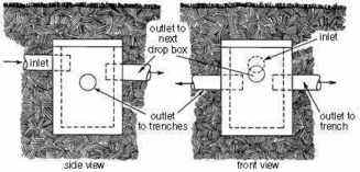
Drop box showing inlet and outlet pipe elevations.
Distribution Boxes
Distribution boxes are used only on level terrain Distribution boxes normally are made from concrete or plastic. They have an inlet and usually three outlets for each of the absorption trenches. The inlet and outlets commonly are 110mm in diameter to accommodate plastic pipe. All of the outlets from the distribution box are set at the same elevation, thus having a base under the box of crushed rock or gravel to keep it level is very important. However, in practice, due to frost action or flooding conditions, keeping all outlets at the same elevation throughout the life of the system is virtually impossible. If the box gets tilted, the trench served by the lowest outlet will receive the greatest amount of effluent. For this reason, distribution boxes may be used only where the elevation of the lowest trench is high enough to back effluent up to the distribution box without surface seepage occurring.
A common sign of problems with a distribution box is if the soil gets soggy over one trench but stays dry over the others. To check for this problem, open the top of the distribution box and check the water flow to the outlets. You may have to dig around the box and level it again. After leveling the box, the outlet going to the trench that was soggy can be plugged temporarily (two to four weeks) so the trench can be rested.
Sewage Mounds
A sewage mound is a special soakaway design used in locations with high water tables (within 1.2m of the surface) and slow infiltration rate soils. A sewage mound takes advantage of the higher infiltration rate of surface soils, compared with subsurface soils. A sewage mound is constructed above the existing ground surface. A mound is basically a high infiltration rate bed set on top of a sand fill that has been spread over the existing ground The high infiltration rate bed is constructed using washed gravel (10 to 20mm) On low infiltration rate soils, the basal area must be large enough to allow percolation of the daily effluent volume into the soil surface. In high water table conditions, the elevated bed allows biological treatment to take place before the effluent infiltrates to the water table.
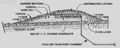
Construction features of a sewage mound.
Effluent is pumped to a mound system and distributed across the rapid infiltration bed under pressure The effluent is pumped to the mound through 1½-inch diameter or larger plastic pipe. The pump tank should be large enough and the pump controls set so a dose equal to about one-fourth of the daily wastewater volume is discharged to the mound when the pump starts. A three-bedroom house has a design load of 1000litres/day, so the pump should discharge about 250litres per dose. This provides a rest period between doses and allows the effluent to infiltrate before the next dose. In addition, it increases pump life. Frequent starting and stopping of a pump will reduce the life of the motor.
Sewage mounds always should be designed with a pressurized effluent distribution system A pressurized distribution system evenly distributes the effluent over the entire basal area and helps prevent overloading in any one spot under the mound.
The pressure distribution system is constructed from either 1¼- or 1½-inch PVC pipe. Pipe diameter is important because too large a diameter (such as 50mm) could result in uneven distribution of the effluent. For a sewage mound requiring a 2metre or narrower rapid infiltration area, two parallel pipes are used. For a sewage mound requiring a 2 to 3 metre wide rapid infiltration area, three parallel pipes are used.
The distribution pipes must have a 6mm diameter hole every 1metre in the bottom of the pipes. The pipe joints and end caps must be glued. Otherwise, they will pull apart during construction, under pressure or later from settling and frost heave. The pipes are connected at the centre where the effluent enters the pressurized distribution system from the pump delivery pipe. If necessary, to protect from freezing conditions, the distribution pipe and delivery pipe must be designed to drain when the pump is off. This can be accomplished by using a ¼-inch diameter weep hole in the delivery pipe in the pump tank.
Sizing
The basal area of the mound (contact area of the fill sand with the existing soil) determines all the other mound design parameters. The basal area is determined by the texture of the existing soil. For slowly permeable clay and clay loam soils, use a design effluent-loading rate of from 8 to 10 litres per day per square metre.
Example: for a three-bedroom house producing 1000litres per day of effluent, the contact area between the fill sand and the existing ground should be between 100sq.m.(1000l/day /10) and 125sq.m (1000l/day/8
The rapid infiltration area is determined using the intake rate of medium sand. Medium sand has a loading rate of 45litres per day per square metre. Using the three-bedroom home example, the required rock bed area is 22.2sq. metres(1000litres per day ÷ 45 litres/day/metre2). For soils with low permeability, keep the effluent distribution pipe width at 1.5 to 2 metres and extend the bed 500mm. either side at the perimeters of the bed i.e., if the pipes are at 2 metres width, the total width of the gravel bed is 3 metres For our three-bedroom home example, the rock bed will be about 22÷ 3= 7.3 metres long. The bed needs to be a min. of 200mm. deep.
Mounds should be located on flat areas or the crests of hills; however, they can be built on sloping terrain. However, soil texture and percolation rate will determine the maximum slope. For example, if the soil texture of the topsoil is clay loam with a V value of 100, then the ground slope should not exceed 1:40 If the percolation rate is between 60 and100, then the ground slope should not exceed 1:20, and if the percolation rate is V = 30 or less, then mounds can be constructed on slopes up to 1:10.
When a mound is constructed on a slope, only the sand-soil contact area under the distribution area (gravel bed) and down-slope from there can be considered basal area. Under sloping soil conditions, the ends and up-slope portion of the mound receive very little effluent and do not contribute to the area of infiltration. The mound, therefore, slopes downhill of the bed.
Construction
Mounds require very diligent and careful construction practices. Mounds have been known to fail due to two main causes -- too small of a basal area for the effluent flow from the house, and poor construction practices. To ensure a mound works as planned, construction practices must be followed very closely. Plus, the homeowner must use water wisely.
The first step in mound construction is to mow the grass or vegetative cover over the basal area to a maximum 50mm height and remove all the cuttings. Then dig in the effluent line from the pumping station. The line must be installed below frost level or sloped uniformly back to the pumping chamber so it drains after the pump shuts off. The excavated trench must be backfilled and the soil firmly compacted to prevent effluent from flowing along the pipe.
Ground preparation comes next. The ground must be ripped or scarified with a chisel plough or the teeth from the backhoe bucket. Once the surface is prepared, no wheel traffic can be allowed in the basal area. Wheel traffic will seal the soil. Do not work in wet soil conditions because wet soil will compact, smear and seal the soil.
Next comes the fill sand. The fill sand should be washed and checked to be sure it contains no more than 10 percent fines. To test, put 60mm of sand in a pint jar and add water until about three-quarters full. Cover and shake to mix the sand and water. Let the mixture stand for an hour and measure the silt and clay accumulation on top of the sand. If the depth is 6mm or less, the sand is clean enough for use in the mound. This test should be done before the sand is delivered to the site
Place the clean sand starting at one end and work toward the other end. Drive on top of the sand as you progress. Shape the sand with a backhoe with tracks or a crawler tractor but make sure you have at least 150mm of sand under the tracks. Wheeled vehicles should not be used for this operation. Do not allow the tracks to run directly on the earth. After forming with the tractor blade, level and do the final shaping by hand. The top of the sand bed should be level the full length of the mound.
For rock beds, a trench about 300mm deep and 3m wide should be formed the required length on top of the sand. Place 100-150mm of 10-20mm washed gravel in the trench. Place the pressure distribution pipe on the rock and cover with 50mm of gravel. Cover the rock with a geotextile material designed for septic system soakaways.
Cap the mound with a loam or loamy sand soil Make the cap 250mm deep and carry the cap down the sides of the mound.
Last, cover the mound with 150mm of good top soil and seed to grass. Don’t plant trees or shrubs on top of the mound. Water-tolerant shrubs may be planted around the base. Permanent lawn sprinkler systems should not be installed near enough to the mound to throw water on it.
Construct mounds to follow the contour of the existing ground. Never place a mound in a low area where water will accumulate. If the mound is on sloping ground, use a drain on the uphill side to divert runoff water around the mound. Mounds can be constructed to complement your landscaping design. Shrubs at the base of the mound will use water and help trap snow.
The trenches must be at least 2 metres apart. Trenches are constructed with a backhoe. Commonly, a 600mm to 900mm wide bucket is used. A wider bucket makes a wider trench that increases the trench bottom area and reduces the length of trench. Do not allow any wheel tracks in the trench since the compaction will seal the surface, greatly reducing the effectiveness of the absorption trench.